- Ditto uses devices running the Ditto SDK (Small Peers) predominantly for data replication across web, mobile, desktop, and Linux-embedded systems, such as a Raspberry Pi, where storage, RAM, and CPU resources are generally static and unchangeable.
- Conversely, you can think of Ditto Server as the cloud worker node, which, although viewed as just another peer in the decentralized peer-to-peer network, is equipped with a replication engine capable of partitioning, sharding, enforcing causal consistency, and more. For a complete list of Ditto Server services that you can incorporate into your architecture, see Key Services.
Data Sync
Key Features
Architecture Overview
Data Replication and Sync Behavior
Ditto Server is a cloud-based component hosted within Ditto’s infrastructure that facilitates data sync across different network scenarios; if a Small Peer has access to the internet, it automatically establishes a connection with Ditto Server to sync. Following is an overview of the network scenarios that Ditto Server facilitates sync for:Key Features
The key characteristics of Ditto Server include:- An authentication service that enables connected devices running the Ditto SDK to obtain valid certificates to participate in the mesh and replicate data they have permissions for.
- A data egress service that you can use to safely consume data created and modified within the Ditto platform by external services and systems. For more information, see Change Data Capture.
- A stateless HTTP API for programmatic data ingress. For more information, see Using the HTTP API to Write to Offline Peers.
Architecture Overview
As illustrated in the following graphic, Ditto Server is a central point of coordination and data storage in the cluster; devices running the Ditto SDK can sync with Ditto Server to propagate changes across disconnected meshes, and even back to the centralized server — your enterprise cloud or datacenter: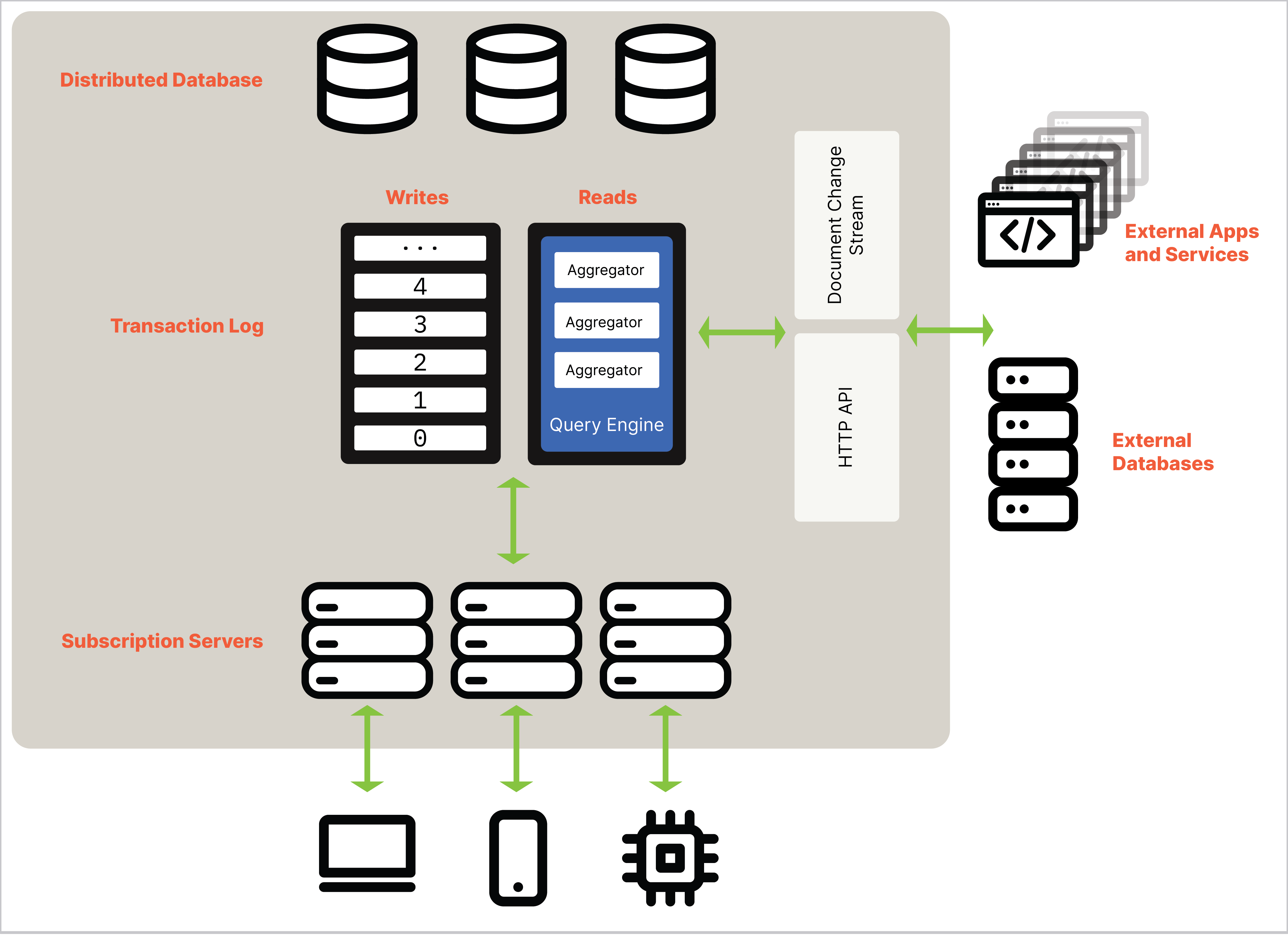
The following graphic provides a high-level overview of the orchestration between the subscription server, transaction log, and distributed database:
Distributed Database
Although Ditto Server appears like any other peer in the peer-to-peer mesh network, internally Ditto Server is a distributed database capable of partitioning and replicating data for scale, performance, and fault tolerance. For more information, see Syncing Data. The distributed database is comprised of core storage nodes distributed across the network. Each storage node runs a local RocksDB open-source embeddable key-value database that stores documents and is capable of automatic indexing. Automatic indexing is a query optimization and data retrieval mechanism that creates, manages, and utilizes the indexes that are distributed across storage nodes. In addition, each storage node has a mapping of partitions to servers, known as an in-memory cluster configuration.Horizontal Scaling
In a Kubernetes environment, as long as Ditto Server has persistent volume capacity to attach a hard drive to the running storage server process, referred to as the stateful sets, Ditto Server scales horizontally. The details of a cluster — including its size, shape, members, partitions, replicas, and more — all reside within a cluster configuration. When a cluster needs to scale up and down, Ditto creates a new cluster configuration and instructs Ditto Server to transition away from the current configuration to the new one. When reconfiguring a cluster, there is minimal data movement. That is, if the cluster grows, the objective is to move only the minimum amount of data necessary to accommodate the new nodes.Subscription Servers
The subscription servers act as soft-state satellite API nodes for receiving and distributing data to devices running the Ditto SDK by functioning as an API gateway in the cluster. That is, the subscription servers bridge the peer-to-peer mesh network and the centralized datacenter or cloud.Summary
As an API gateway, subscription servers are responsible for the following essential functions:- Provide a bridge for devices running the Ditto SDK (Small Peers) to read and write data to Ditto Server, including managing the intricacies of replicating data across peers — Small Peers, as well as Small Peers and Ditto Server.
- Manages authentication, permissions, and document caching.
- If upgraded to the Kafka connector, serves as the producer of transactions for the transaction logs — When the subscription server receives data from a Small Peer, it creates a transaction that contains all of the data from a round of replication and pushes it onto the Kafka log. For more information, see Change Data Capture.
- Working alongside Ditto’s HTTP API, ensures that, regardless of network conditions and internet availability, peers maintain an accurate and up-to-date view of the data.
Soft-State Satellite API Nodes
When a device running the Ditto SDK initially connects to a subscription server, the subscription server triggers a query to determine the current distributed database state. Soft-state nodes play a crucial role as temporary repositories for locally cached data. In scenarios where cached data is comprehensive for a device’s subscription, querying the store nodes might not be required These specialized nodes, functioning as caches, extend Ditto Server’s functionality by bridging communication among all peers and diverse data sources. Additionally, they serve as a means to enhance query performance, leveraging routing keys and data locality. Consequently, the subscription server, when appropriate, “pushes” that data to subscribing peers.Partitioning and Replication
The primary role of Ditto Server is to store datasets that are too large to fit on any one individual device and maintain data synchronicity between all database replicas running locally within devices running the Ditto SDK in end-user environments, such as an iPhone mobile device. From the outside, Ditto Server appears as a single node; however, internally, Ditto Server runs as a distributed database divided into partitions. Each partition consists of a single node in the Kubernetes cluster. If a collection contains many documents stored in a single partition, a single node responds to all of the queries, which has the potential to significantly reduce query performance.Using HTTP API to Write Offline
In serverless environments where you have cloud service reliability of at least 99.99% uptime and therefore high internet access probability, you can use Ditto’s HTTP API to write data from your external system, such as a third-party datacenter or cloud account, to offline Small Peers. When internet connection is dependable and consistent, instead of needing to implement processes like replicating data across the network or caching data to local Small Peer environments in your code, the subscription server facilitates those intricate processes for you. So even when Small Peers are offline, you can operate under the assumption that your update invoked using the HTTP API is consistently available across the platform. For more information, see HTTP API.Managing Local Memory: Garbage Collection
Ditto Server periodically runs the garbage collection (GC) process in an effort to reclaim memory and improve performance by automatically identifying and purging data that is no longer relevant or useful. Ditto Server uses the GC timestamp to determine which document versions are candidates for purge. For more information, see Garbage Collection Timestamp.Managing Queries: Read Transactions
Managing reading and read transactions in distributed systems is complex since you need to consider factors like consistency, isolation, and how to resolve concurrency conflicts. The coordinating node is responsible for managing and coordinating queries within the cluster. Each distributed soft-state storage node maintains a local copy of the partition map retrieved from the cluster configuration. A partition map is a specialized data structure used for managing the propagation of data across partitions within a given cluster. This setup allows any storage node within the cluster to potentially assume the role of a coordinating node when needed.Coordinator Node
The coordinator assesses the query to determine which partitions contain the data necessary to answer the query as follows:- The coordinator compiles a list of required partitions.
- Once compiled, the coordinator then selects one replica from each partition based on a fault-detection mechanism, choosing the replica least likely to have faults.
- The query is sent to each replica, and the results are merged and streamed back to the requester.
For a technical overview of failure detectors, see the academic paper “A Lazy Monitoring Approach for Heartbeat-Style Failure Detectors” by the University of Augsburg.
Random Slicing
Random Slicing has been written about brilliantly in this article by Scott Lystig-Fritchie, which motivates the WHY of Random Slicing as well as explaining the HOW. Here, we will briefly discuss Ditto Server’s implementation. We made a decision to make this first version of Ditto Server as simple as possible, and so we elected to keep our cluster shape and replica placement very simple (though it is extensible and will get richer as time allows or needs dictate). Each document in Ditto Server has a key, or document ID which is made up of a Namespace (The Database (DatabaseId) and the collection) and an ID for the document. Our current hashing policy involves hashing the entire Document ID, ensuring that data within the same Collection resides in the same partition. As per the Random Slicing algorithm, we think of the keyspace as the range 0 to 1. We take the capacity of the cluster, and divide 1 by it. This determines how much of the keyspace each partition owns. In our initial implementation the capacity is the number of partitions we wish to have. We enforce an equal number of replicas per-partition, and thus all clusters are rectangular. E.g. 1*1, or 2*3, or 5*2, etc., where the first number is the number of partitions, and the second the number of replicas. Random Slicing allows in future to have heterogeneous nodes, assigning the capacity accordingly. In the case that we want three partitions of two replicas, we say each partition takes 1/3 of the keyspace, or has 1/3 of the capacity. Hashing a DocumentId then gives us a number that falls into the 1st, 2nd or 3rd 1/3 of the keyspace, and that decides which partition owns that document. We can transition from any configuration to any other, and we do this by slicing or coalescing partitions using the Cut-Shift algorithm from the Random Slicing paper. The graphic below illustrates how this looks.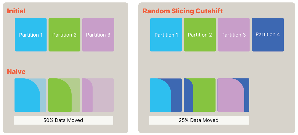
Interval Maps, Missed Transactions, and Backfill
Each storage nodes keeps a local data structure, stored durably and atomically with the document data, that records what transactions the node has observed. The structure is called theIntervalMap, and represents what has been observed, in what slices of the keyspace.
For example, if a server is responsible for an interval of the keyspace that represents the first third of the keyspace, the server “splices” the observed transactions into the IntervalMap at that interval.
Imagine Server 1 is responsible for Interval 1, it receives transactions 1..=100 from the log, it adds the data from those transactions to a local write transaction with RocksDB. Then it splices the information into the IntervalMap, that it has seen a block of transactions from 1..=100. We now say that the base for Interval 1 is 100. Now the server stores this updated IntervalMap with the data in a write transaction to RocksDB.
Next the server receives transaction 150..=200 from the log. Clearly the server can detect that it has somehow missed transaction 101..=149. The server can still observe and record the data from these new transactions, and splice the information into the IntervalMap. The IntervalMap now has a base of 100 and a detached-range of 150..=200.
Any server with any detached ranges can look in the Partition Map to see if it has any peer replicas, and ask them for the detached range(s). This is an internal query in Ditto Server. If a peer replica has some or all of the missing transaction data, it will send it to the requesting server, who will splice the results in the IntervalMap, and write the data to disk. This way a server can recover any data it missed, assuming at least one replica stored that data. We call this Backfill.
Nodes gossip their IntervalMaps, this is how the UST is calculated, and how Backfill replicas can be chosen.
Read on down to “Missed/Lost Data” if you want to know how the cluster continues to make progress and function in the disastrous case that all replicas miss a transaction.
The IntervalMap, gossip, Backfill, UST, Read Transactions, and the GC timestamp all come together to facilitate “transitions”, which is how Ditto Server can scale up and down, while remaining operational, available, and consistent.
Transitions
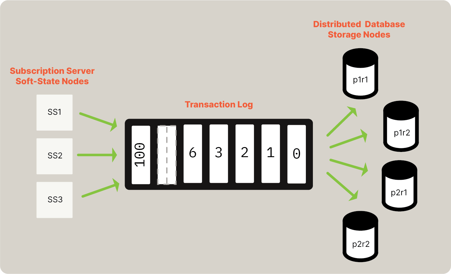
Also mentioned in Scott’s article on Random Slicing is the fact that Random Slicing will not tell you how, or when, to move your data around if you want to go from one set of partitions to another. In Ditto Server we have the added problem that we must at all times remain Causally Consistent. Ditto Server manages Transitions between configurations by leaning on those two primitives the UST and the GC Timestamp. The process is best explained with an example. Using the diagram from the Random Slicing section, a walkthrough of the transition from the three-partition original cluster to the target four-partition cluster. In this case assume two replicas per partition, which means adding two new servers to the cluster. There is a Current Config, that contains the intervals that make up the partitions 1, 2, and 3 mapped to the replicas for those partitions. The namep1r1 refers to the first replica of Partition 1, p2r2 the second replica of Partition 2, etc.
In the Current Config there are nodes p1r1, p1r2, p2r1, p2r2, p3r1, p3r2. Two new nodes are started, (p4r1, p4r2). A new Cluster Configuration is generated from the Current Configuration. This runs the Cut-Shift algorithm and produces a Next Configuration, with the partition map and intervals as-per the diagram above.
We store the Current Config, and the Next Config in a strongly consistent metadata store. Updating the metadata store causes the Current Config and Next Config file to be written to location on disk for each Ditto Server Store node, and each node is signaled to re-read the configs.
The servers in p1-p3 are all in the Current Config, and the Next Config. The servers in p4 are only in the Next Config.
A server will consume from the log if it is in either config. Those in both configs will store data in all intervals they own in both configs. In our example each of the current config servers stores a subset of the current sub-interval of its current ownership in the next config. The new servers in p4 start to consume from the log at once, and gossip to all their peers in both configs.
Backfill (Again)
For example, we start the new servers when the oldest transaction available on the log isTxn Id 1000. They must Backfill from 0-1000 from the owners of their intervals in the Current Configuration. They use the Current Configuration to calculate those owners, and the IntervalMaps from gossip to pick an owner to query for data no longer on the log. Recall that the UST is calculated from the base of the IntervalMap but these new servers (only part of the new config) do not contribute to the UST until they have Backfilled.
Routing and UST
In the section on UST we described a scalar value, the Transaction Timestamp. In reality this value is a pair of the ConfigurationId and the UST. The ConfigurationId rises monotonically, the initial Configuration being ConfigId 1, the second ConfigId 2, etc. This allows us to calculate a UST per-configuration. Before we began the transition the UST was (1, 1000). The UST may never go backwards (that would break Causal Consistency). After starting the new servers and notifying nodes about the Next Config, the UST in the Current Config is (1, 1000) and in the Next Config is (2, 0). During this period of transition the nodes in p4 cannot be routed to for querying. Only nodes in the Current Config can coordinate queries, and these nodes decide what Configuration to use for Routing based on the USTs in each of the Current and Next Config. We call this the Routing Config. It is calculated. And like everything else in Ditto Server, it progresses monotonically upwards. After the new nodes have Backfilled, and after some period of gossip, the UST in the Next Config arrives at a value that is >= the UST in the current config* so the servers in the Current Config will begin to Route queries using the Next Config. Recall that nodes gossip a GC timestamp that is based on active Read Transactions. A Read Transaction is identified by the Timestamp at which it began. For example (1, 1000) is a Read Transaction that began at UST 1000 in the Current Configuration. When all the replicas in the Current Configuration are Routing with the next configuration, (e.g., the Cluster GC timestamp is in the Next Configuration, (2, 1300)) the Transition is complete. Any of the nodes can store the Next Config into the Strongly Consistent metadata store as the Current Config. Each node is signaled, and eventually all will have a Current Config with ConfigId 2, and will forget metadata related to ConfigId 1. Furthermore, Garbage Collection will ensure that replicas drop data that they no longer own.Transaction Log
As a core part of Ditto, transaction logs capture information about changes made to the local Ditto store for each transaction, including the type of transactional operation performed, such as upsert, remove, and so on.Enforcing Causal Consistency
Ditto Server’s replication engine uses this transaction log to enforce causal consistency by identifying each transaction’s sequence and execution time as follows:If upgraded to the Kafka premium option, Ditto Server utilizes the Kafka commit log as its underlying data structure for storing and processing messages from your Kafka queue. For more information, see Change Data Capture.
- When the transaction is committed, the sequence number represents the current version of the database. In the transaction log, a transaction’s execution sequence number becomes the transaction timestamp, which reflects the UST (timestamp). For more information, see Timestamps.
- The logged transaction timestamps form a total sequence: From zero and above.
In this context, “zero” refers to the initial state of the datastore, in which no data is present.
Gossipping for High Availability
In decentralized communication, each node gossips its highest transaction committed. Background gossip refers to the communication between nodes to share information about their state without relying on a centralized authority. The gossiped data is encapsulated in anAnnounce message, which contains the announcing server’s IntervalMap, GC timestamp, highest observed ClusterConfig epoch, and a boolean that indicates if the server has backfilled in that ClusterConfig epoch.
The IntervalMap is a mapping from ranges of document IDs, referred to as intervals, to TransactionSets. The IntervalMap expresses exactly which transactions have been applied in which intervals.
From this gossip, individual nodes calculate what they consider to be the UST. If every server gossips its local maximum committed transaction, then the UST is the minimum of those maximums.
The local maximum committed transaction refers to the process in which a node shares information about the highest transaction it has committed to its local storage. Put differently, the UST represents a limit that should not be exceeded — the “upper limit.”
For more information, see Timestamps.